Introduction
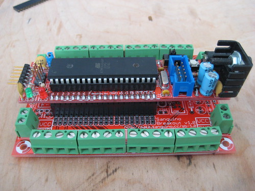
This is the Sanguino Breakout Shield board. It is primarily intended as a shield for existing Sanguino boards, but we've also included the footprint for a full Sanguino on the PCB as well. Its up to you as the builder to decide what shape the board should take: You can build it as a single board with an integrated Sanguino, or you can add headers that allow you to plug an existing Sanguino into the board. its your choice!
The Sanguino itself has some awesome features like:
- 64K of flash space
- 4K of RAM
- 2K of EEPROM
- 2 hardware serial ports
- 32 GPIO pins
- 6 PWM pins
- 8 analog pins
- I2C, SPI, etc.
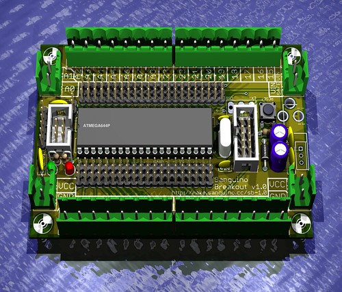
PCB
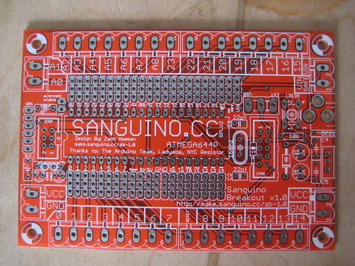
This is the Sanguino Breakout Shield PCB. You can download the files used to make it at the bottom of the page.
Components
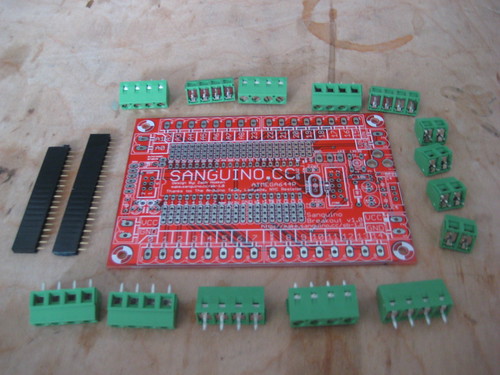
Bill of Materials
Make It!
Before you solder a single component to the board, you need to decide how you are going to build your Sanguino Breakout Shield. There are two different options:
- Build it as a shield that you can plug an existing Sanguino into. This is the best way if you already have a Sanguino, or you want to be able to use your Sanguino in a different project.
- Build it as a complete board that contains a Sanguino. This is good if you do not already have a Sanguino, or you know you are only going to use your Sanguino in this board.
Once you've decided which way to build the board, continue on to the relevant instructions:
Sanguino Breakout v1.0 Kit Shield Assembly Instructions
Sanguino Breakout v1.0 Kit Complete Assembly Instructions (not done yet)
Use It!
Software
The Sanguino is compatible with Arduino, meaning that with slight modifications, the Arduino host software can be used to program and upload sketches to the Sanguino. In order to do that, you should check out the page on using your Sanguino which describes setting up the software and how to program for it.
Prototyping / Semi-permanent Installations
This shield is perfect for both prototyping and semi-permanent installations. The screw terminals provide a fast and fairly reliable connection. Since it also have 4 screw holes, its quite easy to mount the breakout shield to your project as well.
Files
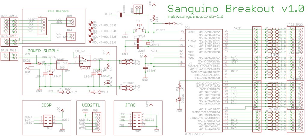
Schematic
Eagle Files
The files used to make this board are available from Google Code
They contain:
- Eagle schematic and board layout
- GERBER files used to manufacture board
- 3D rendering of circuit
- POVRay scene file of circuit
- PDF outputs of circuit
- PS outputs of circuit
- PNG outputs of circuit
Project Hosting
This project uses Google Code to host our project release files. You can view a list of the latest files here
Subversion
All of the latest, up-to-date files are stored in Subversion